A whirlwind tour of the Cloud Integrated Advanced Orchestrator
The Cloud Integrated Advanced Orchestrator (CIAO) is designed to be a simple IAAS solution for creating private clouds within an enterprise. A CIAO cluster is composed of a number of different computing devices referred to as nodes. It can be used to deploy units of computation, known as instances, across its nodes. Once deployed, instances can be monitored and managed. Two types of instances are supported; VM based instances, in which all computation is performed inside a hypervisor, and container instances, in which docker containers are run directly on the cluster nodes.
Instances are created from workloads and images. A workload is a set of instructions for creating instances of a particular type. They, for example, specify the type of instance to be created, i.e., VM or container, its CPU, memory and storage requirements, its backing image and a set of instructions to run inside the instance when it is started. Multiple instances can be created from the same workload. Each instance has its own disk image that contains the instance’s rootfs. This disk image is derived from the backing image specified in the workload from which it was created. For VM instances, both the instance image and the backing image are stored in a ceph cluster. For container images, the backing image refers to a docker container image supplied by a docker registry. Both the container backing image and the container rootfs image are stored locally on the compute node on which the container runs. Additional data volumes can be created in the ceph cluster and attached to both container and VM instances at either creation time or at a later date.
Instances, workloads and images are created inside constructs called tenants. While the instance is the unit of computation, the tenant is the unit of isolation. Instances running in the same tenant are connected together on a tenant private network. Instances that are part of the same tenant can talk to each other but those that are part of different tenants, by default, cannot. This holds true even if two instances from different tenants happen to be running on the same compute node. Workloads and images are also, by default, private to the tenants in which they were created, although it is possible to create public workloads and images that can be used and shared across all tenants.
If the cluster is connected to an external network, instances will be able to access services running in that external network. Although, external client applications will not be able to see or talk to instances by default, instances can be exposed to the outside world by assigning external IP addresses to them, as we shall see below.
Once launched, an instance can be stopped and restarted. Stopped instances typically lose the association with the node on which they previously ran. By stopping and restarting an instance you migrate it from one node to another. Any data stored in data volumes, and for VMs any data stored in rootfs volumes, will be migrated intact with the instance. Instances also retain their network configuration, e.g., their IP addresses, when migrated from one host to another. Live migration is not supported. Entire nodes can be evacuated of all of their instances in a single command. This is useful if a node needs to be temporarily removed from the cluster for maintenance.
Two levels of privilege are defined; user level and administrator level. Users can perform many actions including creating and destroying instances, images and volumes. However, certain actions are restricted to administrators. Examples of operations that require administrator level access include creating public workloads and images and evacuating nodes.
Finally, quotas can be applied to a tenant by cluster administrators limiting the number of instances, volumes, images and resources that can be consumed by that tenant.
Nodes and services
A Cloud Integrated Advanced Orchestrator cluster is composed of one or more nodes. These nodes host the cluster’s control plane and its instances. Three different types of nodes are defined; master, compute and network. The control plane consists of four different types of services; controller, scheduler, launcher and cnci-agent.
Controller and scheduler run on the master node. Controller maintains the cluster state and provides a public REST API that can be used to construct and maintain the cluster. Scheduler acts as a central hub for the cluster, routing control plane traffic to and from its various services. At the time of writing, only one instance of both controller and scheduler run at any one time. They are usually co-located on the same node and so typically, there is only one master node per cluster, although it is technically possible to have two master nodes, one running controller, the other scheduler.
Launcher is responsible for launching, monitoring and managing instances. One launcher service runs on each compute node. Launcher shares its compute node with the instances that it creates and manages.
The final component of the control plane, cnci-agent, runs inside a special type of VM instance called a Compute Node Concentrator Instance (CNCI). CNCI instances run solely on network nodes. They share their network nodes with a launcher instance that creates and manages them. Each network node can support multiple CNCIs. A CNCI is itself a VM instance. It contains a component called cnci-agent which is integral to setting up, connecting and maintaining the cluster’s networks. CNCI instances, and networking in general, will be discussed in much greater detail below.
All communication between these services is encrypted and takes place over a protocol called Simple and Secure Node Transfer Protocol (SSNTP).
Finally, a command line tool, ciao, is provided that can be used by end users and administrators to interact with the cluster.
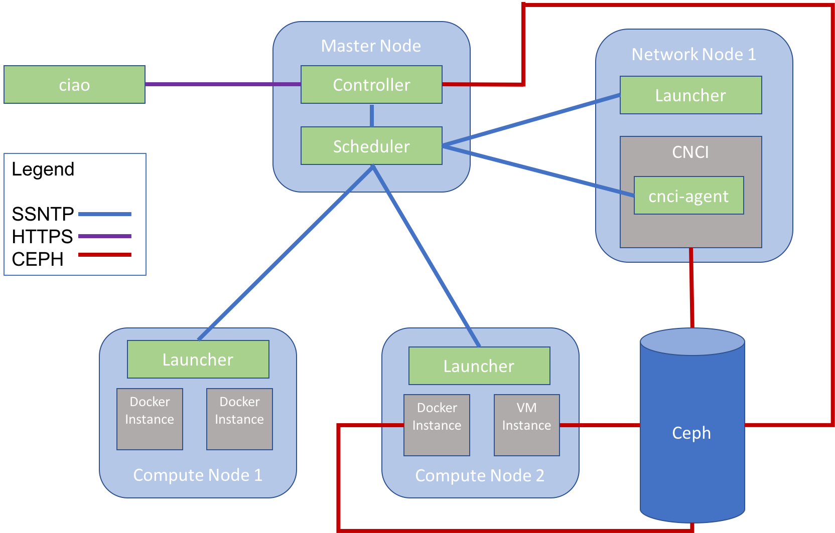
Figure 1 illustrates how the various components of a simple cluster fit together. The image depicts a cluster with one master node, one network node and two compute nodes. The master node runs scheduler and controller. Launcher runs on both the compute nodes and the network node. There are four compute instances, two on each compute node, and one CNCI. Inside the CNCI the final service, cnci-agent, runs. All the services communicate with each other via scheduler using the SSNTP protocol. Controller, the VM compute instance and the CNCI also communicate with the ceph cluster. The rootfs images for the VM instance and the CNCI were originally created by controller and are stored in ceph. One of the docker instances also needs to communicate with the ceph cluster as it has a data volume attached to it. Finally, the user inspects and manipulates the cluster using the ciao tool which executes the user’s commands by communicating over HTTPS via controller.
We’ll take a closer look at the CIAO services, their communication protocol and the user focused ciao tool in the next few sections.
Ciao tool
Users and administrators interact with the cluster using a command line tool called ciao. This tool can be used to perform all the available operations on the cluster. The ciao tool itself is little more than a front end that maps users’ requests onto a REST API and sends these requests to controller. The ciao tool and controller communicate via HTTPS only. For examples of some ciao commands please see The command line.
Controller
Controller is the central management entity for the cluster. It provides a REST API that can be used to inspect and manipulate the cluster, it processes and validates users’ requests received via this API and it maintains the cluster state. Controller keeps track of the cluster’s tenants, workloads, images, instances and volumes. Although controller can process some commands it receives by itself, such as creating a new image, it needs help fulfilling other commands such as starting or stopping an instance or creating a tenant. To perform these other actions controller needs to communicate with the other services in the cluster’s control plane.
Launcher
One launcher instance runs on each compute and network node. Launcher is responsible for creating and managing the lifecycles of compute and CNCI instances. It also monitors the state of the node on which it runs and the instances it manages sending information about these instances back to controller and scheduler on a regular basis. Launcher keeps track of the available resources on its node, and if it determines that resources are too low, will report to scheduler that it is full and cannot host any new instances for the time being.
Scheduler
Scheduler serves three purposes:
- It acts as the communication hub for the cluster’s control plane. It routes SSNTP traffic between two services that need to communicate with each other.
- It determines on which nodes a new instance should be launched. The choice of node is based on various scheduling decisions including the load of the various nodes, as reported by launcher, and any workload specific scheduling instructions.
- It informs the other services of any cluster wide configuration settings.
Simple and Secure Node Transfer Protocol (SSNTP)
SSNTP is a custom TLS based asynchronous messaging protocol that is used by all the services in a Cloud Integrated Advanced Orchestrator cluster to communicate with each other. SSNTP is a client/server protocol. There is currently only one server in a cluster, scheduler. All of the other services, i.e., launcher, controller and cnci-agent are SSNTP clients and connect to scheduler.
SSNTP is secure. Two-way certificate based authentication is performed when a client connects to scheduler and traffic between clients and scheduler is encrypted.
SSNTP clients and servers communicate by sending messages to each other. Messages can be sent by either client or server. An SSNTP message consists of a binary header followed by an optional YAML encoded payload. SSNTP messages are asynchronous. This means that the sender of a message does not normally wait for a response to the message once it has been sent. The protocol is purposely designed this way to mirror the communication architecture of the Cloud Integrated Advanced Orchestrator (CIAO). In a CIAO cluster most of the control plane messages are status and statistic messages sent from the compute and network nodes by launcher services to controller. These messages are sent either periodically or when some significant event occurs on the node. The messages are not solicited by controller nor does launcher care whether controller correctly receives them. The asynchronous nature of the majority of the control plane communication is best served by an asynchronous protocol, a role which SSNTP nicely fulfils.
Note that in some circumstances a response is required to an SSNTP message. For example, consider the case in which controller sends a message to launcher to start a new instance. Controller is actually interested in whether the instance started correctly, and if it failed, the reason for its failure. In this case launcher will send controller a start failure message for any instances that failed to launch.
For more information about SSNTP the reader is referred to SSNTP.
Networking
The Cloud Integrated Advanced Orchestrator is supplied with an innovative Software Defined Network (SDN) solution that provides simple to use and secure networking. Highlights of this SDN are as follows:
- Each tenant gets its own private network.
- VM and container instances communicate seamlessly over this private network.
- Instances can discover each other by performing DNS lookups against tenant local DNS servers.
- Instances can communicate with the outside world, but by default, cannot be accessed by entities outside the cluster or running in different tenants.
All this functionality comes for free and requires no configuration by the end user.
Instances can of course be made accessible to the outside world and to other tenants but setting this up does require some input by the end user. The administrator needs to create a pool of external IP addresses, essentially a range of IP addresses that have been allocated for use by the cluster, and then assign these IP addresses to the instances that need to be exposed. This can be done by issuing a few simple commands as illustrated in the Creating your first cloud app tutorial.
Compute Node Concentrator Instances (CNCIs)
At the heart of the Cloud Integrated Advanced Orchestrator’s networking model are the CNCIs. CNCIs are responsible for ensuring that instances can communicate both with each other and with the outside world. In short they:
- allow instances that are part of the same tenant but hosted on different nodes to communicate
- allow instances to communicate with the outside world
- contain local DHCP and DNS servers providing instances with their own private IP addresses and associating these address with instance names
- provide SSH access to VM instances
- allow external entities to connect to instances via external IP addresses
CNCIs are a special type of instance. Like normal instances, they are started by launcher, but they differ from these instances in a number of ways:
- They run on a special type of node called a network node. Network nodes are members of the CIAO cluster dedicated to running CNCI instances. They do not host normal instances or any of the control plane services.
- They are not visible to users.
- They are created on demand when the user issues a command that requires a CNCI, e.g., creates a new instance.
- Unlike normal instances, CNCIs are automatically restarted if they exit or fail.
- CNCIs are assigned a public IP address from an external (corporate) DHCP server.
- CNCIs self-terminate if they are no longer needed.
CNCIs are created from a private image and workload definition that are not visible to users. The image is built on the latest Clear Linux release and, as we have seen, contains a cnci-agent that communicates with scheduler and manages the CNCI’s services.
Cloud Integrated Advanced Orchestrator cluster of any non-trivial size will typically have more than one CNCI running at any one time. We’ll explore how and why these CNCI instances get created in the following section.
Subnets
A new IP address is allocated to an instance when that instance is created. These IP addresses are allocated from an existing subnet that is assigned to the tenant. If a tenant does not yet have a subnet assigned to it, or all of the IP addresses in its existing subnets are allocated, a new subnet is created for that tenant. By default, the size of the subnet is set to 256. Three of the IP addresses in each subnet are reserved for the network address, the broadcast address and the subnet gateway. This leaves 253 addresses free for instances.
The default subnet size for a given tenant can be changed by an administrator. The main reason to alter the default subnet size is CNCI scaling. A new CNCI instance is created for each subnet. With the default settings, each CNCI will support up to 253 instances. Thus, it could be possible to have a situation in which both external and inter-node traffic for 253 instances is routed through a single CNCI. Depending on your network bandwidth requirements, the CNCI could end up being a bottleneck. In such circumstances, the bottleneck can be alleviated by using a smaller subnet size for the tenant. Conversely, if your workloads do not generate or accept much network traffic it might be better to choose a larger subnet size to reduce the load on the cluster’s network nodes. The maximum subnet size is 1048576 and the minimum is 4. Remember, when using a subnet size of 4, only one IP address is available to instances. In this scenario you would end up a 1 to 1 mapping between CNCIs and instances, which is probably excessive.
Taps, tunnels, gateways and bridges
The previous sections introduced the concept of a CNCI that allows instances to communicate with each other and the outside world. However, they skimmed over the details of how this actually works in practice. In this section we’ll dig a little deeper into the Cloud Integrated Advanced Orchestrator’s SDN solution and see how all the various network constructs are created and connected together.
Let’s start with TAP devices. A new virtual network interface (TAP device) is created for each instance on the compute node on which it resides. An IP address is assigned to this network interface. This IP address is private to the tenant to which the instance belongs, i.e., it can be used to access that instance from any other instances running in the same tenant, but cannot be used to access that instance from outside the cluster or from an instance residing in a different tenant.
Bridges are created on each compute node for each of the subnets in use on that node. A subnet is deemed to be in use on a node if an instance belonging to the subnet is running on that node. Instances from the same subnet running on the same node can talk to each other via this bridge. The traffic never leaves the compute node. However, traffic destined for devices external to the cluster or subnet or for instances that are running on other nodes, is routed via a CNCI. Communication between an instance and a CNCI takes place over a GRE tunnel.
One GRE tunnel end point is created on a compute node for each subnet in use by that compute node. The other end point of the tunnel exists inside the CNCI itself. This tunnel, and any other tunnels corresponding to the same subnet used on different compute nodes, are connected to the subnet gateway which exists inside the CNCI. A dnsmasq instance, providing DHCP and DNS services, is maintained for each subnet by the CNCI and is also attached to the gateway.
Figure 2 depicts how this all fits together and how in particular two instances connected to the same subnet on both the same and different nodes communicate together.
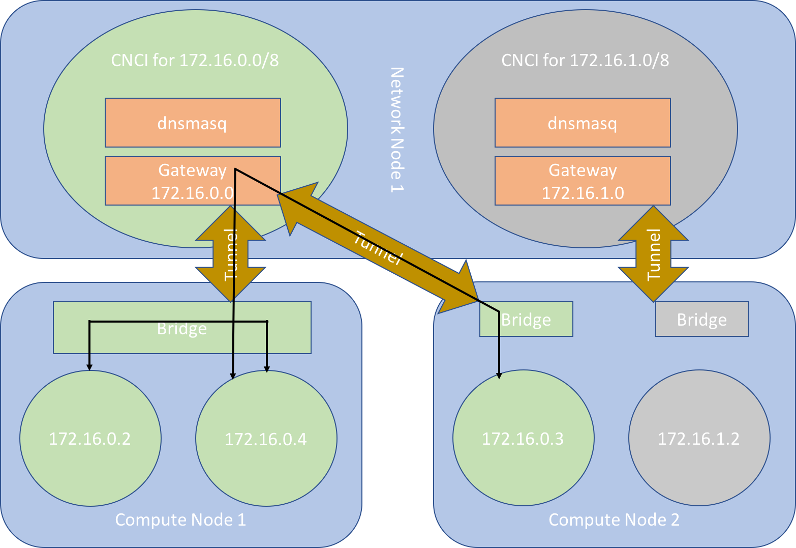
In this simple cluster we have two compute nodes and one network node. There are two separate tenants. Instances from tenant 1, coloured green, run on both compute node 1 and compute node 2. There is only one instance in tenant 2, coloured grey, and this runs on compute node 2. Each tenant has a single 8 bit subnet, 172.16.0.0/24 for tenant 1 and 172.16.1.0/24 for tenant 2. Each instance is connected to a local subnet bridge running on their local compute node and to their subnet gateway inside their CNCI via a GRE tunnel. The instances are assigned their IP addresses from the dnsmasq instance running in the CNCI to which they are connected. The two instances from tenant 1 running on compute node 1 can communicate with each other directly via the bridge. Instances 172.16.0.4 and 172.16.0.3 are part of the same tenant but run on different compute nodes. Therefore, they communicate with each other via the CNCI. The instance from tenant 2, 172.16.1.2, is on its own private network and cannot communicate with or be seen by the other two instances.
Multiple subnets
A single tenant containing instances whose IP addresses are allocated from multiple subnets will be served by multiple CNCIs, one per subnet. To ensure that instances from different subnets can communicate with each other, special handling is needed to connect CNCIs belonging to the same tenant to each other.
The cnci-agent running inside each CNCI is informed by controller about the other CNCIs that belong to the same tenant. Each time controller adds or deletes a subnet ( and a CNCI ) it sends an SSNTP message to each cnci-agent in the tenant providing the latest information about the tenant’s subnet configuration. The cnci-agents use this information to maintain a network of multi-point GRE tunnels, that connect the CNCIs in the same tenant to each other. When an instance needs to talk to another instance in the same tenant but a different subnet, its packets flow from its compute node to its CNCI. They are then re-routed by this CNCI through a GRE tunnel connected to the CNCI that manages the subnet of the target instance. This CNCI routes the packets through the GRE tunnel that leads to the compute node on which the target instance runs. Note that this may actually be the same compute node as the first instance. Communication between two subnets always flows through a CNCI, or rather two CNCIs, even if these communicating instances are resident on the same physical compute node.
When a cnci-agent receives information about neighbouring CNCIs it performs a number of actions:
- It creates a multi-point GRE tunnel, if it does not already exist, and assigns this tunnel an IP address. By default, this IP address is chosen from the subnet 192.168.128.0/17, but this is configurable.
- It adds routing rules so traffic destined for the tenant private addresses of instances belonging to other subnets are routed through this tunnel and directed to the virtual IP address of the tunnel endpoint on the target CNCI.
- It updates the ARP cache on the CNCI to map between the real physical IP addresses of the neighbouring CNCIs and the virtual IP addresses assigned to the endpoints of their multi-point GRE tunnels. In this way the IP addresses of the remote tunnels are resolved to the IP addresses of the CNCIs on which they are hosted.
It is important to note that tenants consisting of multiple subnets contain multiple independent L2 networks. Packets from one L2 network destined for another, leave their L2 network in their CNCI and are routed over the L3 network to the target L2 network via a CNCI to CNCI tunnel, as we have seen. This is in contrast to tenants consisting of a single subnet in which all inter-instance communication typically takes place on the same virtual L2 network.
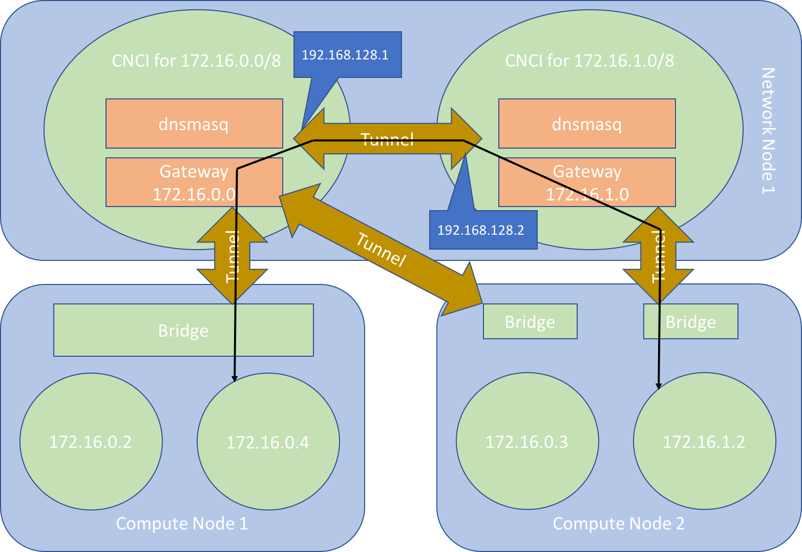
Figure 3 illustrates how multiple subnets work in practice. The cluster depicted is similar to the cluster presented in Figure 2. As in Figure 2 we have one network node, two compute nodes, two CNCIs and two different subnets. However, in Figure 3, there is only one tenant. Both subnets belong to this tenant. The image depicts how an instance, 172.16.0.4, in one subnet, communicates with another instance, 172.16.1.2, in a different subnet. The communication takes place via the CNCI of the first instance, a tunnel connecting this CNCI to the CNCI of the second instance and a tunnel connecting the second CNCI to the compute node hosting this second instance.
External traffic
Network nodes are expected to have at least one network interface connected to an external network of some kind. When a new CNCI is launched on a network node a macvtap interface is created for it. This interface is associated with the network node’s external network interface. The CNCI instance receives an IP address on the external network via DHCP. All external traffic entering and leaving a subnet flows through the CNCI’s macvtap network interface. Figure 4, demonstrates the two different types of external network access possible.
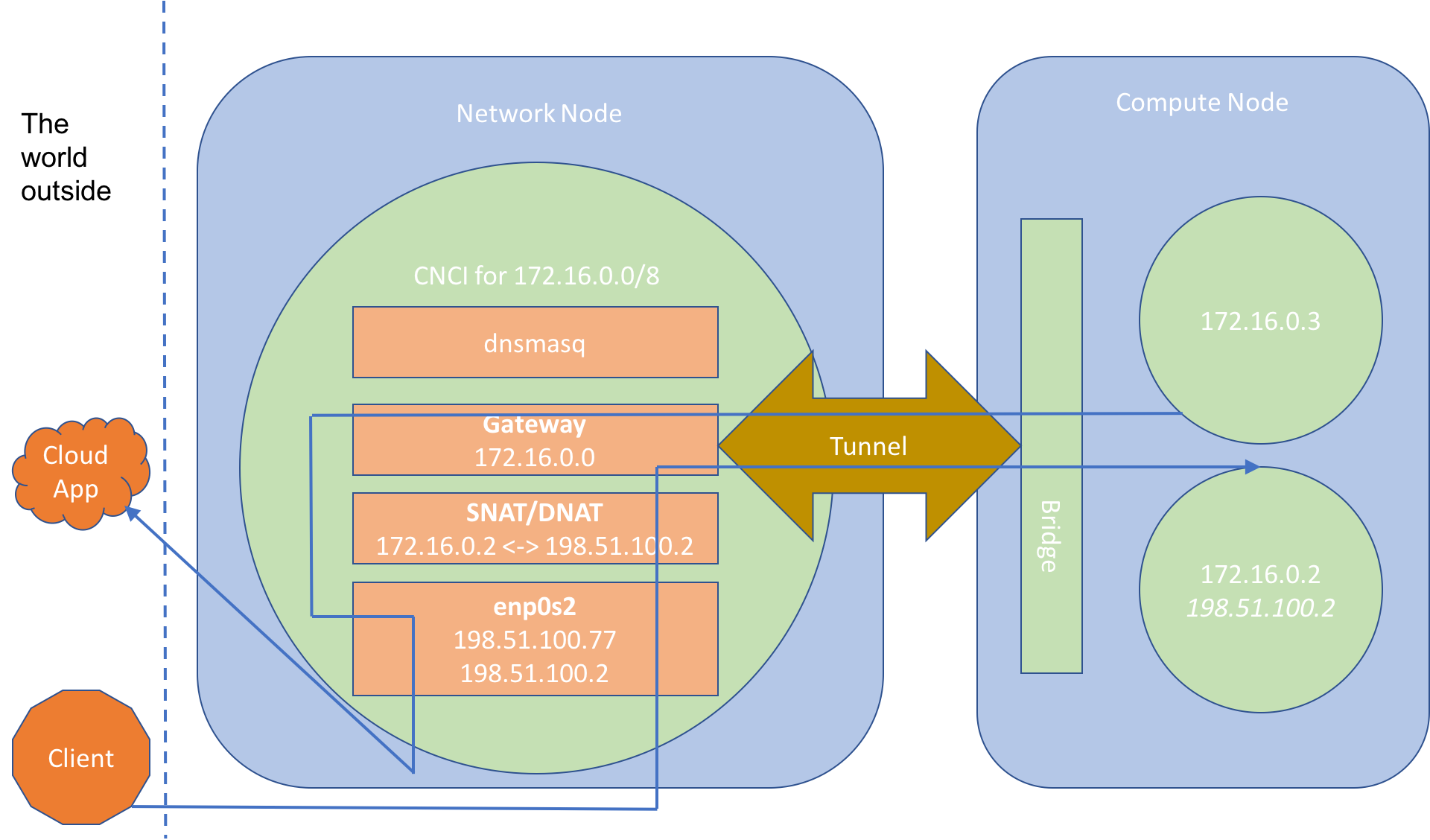
The figure depicts one network node and one compute node. The network node hosts a single CNCI for the subnet 172.16.0.0/24. The network interface of the CNCI has been assigned an IP address of 198.51.100.77. This IP address is visible to the external network.
Two instances have been created and are both assigned to the same tenant and subnet. The instances have internal IP addresses of 172.16.0.2 and 172.16.0.3. The 172.16.0.2 instance also has an external IP address assigned to it. In the diagram, the instance without the external IP address, tries to access some sort of cloud application running in the external network. Network traffic initiating from this instance flows from the bridge through the GRE tunnel into the CNCI’s subnet gateway. The IP packets are NATed as they flow through the CNCI’s network stack and out of its network interface. Upon reaching the cloud application they appear to have originated from the CNCI itself. Instance 172.16.0.3 can initiate external connections but is itself invisible to the outside world.
Instance 172.16.0.2 is a little different. It has been assigned an external IP address of 198.51.100.2. When an instance is assigned an external IP address two modifications are made to the CNCI to which that instance is connected:
- DNAT and SNAT iptables rules are set up on the CNCI to translate between the instance’s internal and external IP address, in this case between 172.16.0.2 and 198.51.100.2.
- The external IP address is added to the network interface of the CNCI making the IP address visible on the external network.
When an external client tries to connect to 198.51.100.2 its network packets arrive at the network interface of the CNCI, with which the external IP address 198.51.100.2 is associated. The destination address of the IP packets is then translated by an IP table rule from 198.51.100.2 to 172.16.0.2. The traffic then makes its way through the subnet gateway and the GRE tunnel to the instance running on the compute node. The reverse process happens when an instance with an external IP address tries to connect to an external device. The packets flow through the tunnel, the subnet gateway and the CNCI’s network card to the outside world. The source address of these packets is rewritten from the internal address to the external IP address, i.e., from 172.16.0.2 to 198.51.100.2, and not the IP address of the CNCI, 198.51.100.77.
Docker
A nice feature of the Cloud Integrated Advanced Orchestrator’s SDN is that containers and VMs can communicate with each other on their private tenant networks. This inter-instance-type communication comes for free. No special configuration is required by the user or the cluster administrator. An example of container and VM networking can be seen in the tutorial.
Seamless container and VM networking is achieved as follows. Containers, like VMs, are assigned to a subnet and allocated an IP address from that subnet. A separate docker network is created on each compute node for each subnet that is used by a container running on that node. Before launcher creates a new container on a compute node it checks to see if the docker network corresponding to that subnet already exists. If it doesn’t, launcher creates the network. The container is itself associated with this network by launcher when it is created.
All of these docker subnet networks use a custom network driver called ciao. The ciao network driver is hosted by launcher and implements two docker network plugins; NetworkDriver and IpamDriver. By implementing this driver, launcher is acting as both a docker network and a docker IPAM plugin. These plugins simply map docker networking identifiers and concepts onto the networking model of the Cloud Integrated Advanced Orchestrator. For example, when docker creates a new container it will invoke the CreateEndpoint handler on the network plugin. This handler is supposed to create a new network interface for the container. This interface will have already been created in advance by launcher, so the ciao network driver’s implementation of CreateEndpoint simply locates the existing interface and returns information about this interface to docker. The identifiers for various network constructs such as subnets and interfaces are assigned names from different namespaces by both the Cloud Integrated Advanced Orchestrator and docker. The ciao network driver maintains a database so that it can translate identifiers from one namespace to another.
Storage
The Cloud Integrated Advanced Orchestrater supports two forms of storage for instances:
- local storage, in which an instance’s data, including its rootfs, is stored on the disk of the node upon which the instance is hosted
- ceph based storage, in which an instance’s data is stored in the ceph cluster.
Both the rootfs and any disk based data written or read by a VM instance must be stored in a ceph volume. This is in contrast to containers, whose root file systems are always stored on the node on which the container is hosted. Processes running within these containers can write to the containers’ root file systems. Although, disk based IO will be very fast in containers that read and write to their rootfs, there is a downside. Any data written to a local volume does not survive migration. The rootfs of a container is reset to its default state when it is migrated from one node to another. It is however possible to create a data volume inside the ceph cluster and attach this volume to a container. Any data written to this volume by the container will survive migration.
Images
The controller implements an image service. This service manages a set of RBD (Rados Block Device) volumes that serve as backing images for the root file systems of newly created VM instances. The image service allows users to create, delete, inspect and enumerate images. Normal users can create tenant private images, i.e., images that are associated with a given tenant and can only be used to create root file systems for instances belonging to the same tenant. Administrators can create public images, that that can be used by all users to create VM instances in any tenants they like.
When a new image is uploaded to the image service it is converted into a raw format and stored in a new RBD volume in the ceph cluster. An RBD snapshot is then taken of this new volume and the snapshot is protected. It is this protected RBD snapshot that is used as the backing image for VM instances. Users must specify a name when they create an image. The controller will also assign the newly created image an UUID. The image can be referred to by either its name or UUID.
In order to create an instance that uses an image in the image service as the backing image for its rootfs, the backing image can be referenced in the workload definition used to create the instance. When the controller creates the new VM, it first creates its rootfs, by making a copy-on-write clone of the protected snapshot that represents the backing image. This results in a new CIAO volume. Volumes are discussed further in the following section.
Volumes
The controller implements a volume service that manages a set of volumes. Volumes are used for two purposes:
- They serve as the root file systems of VM instances.
- They can be used by both VM and container instances to store data.
The volume service allows volumes to be created, enumerated, inspected, attached and detached from existing instances. A volume can only be attached to one instance at any one time.
Volumes can be attached to both container and VM instances at creation time, via a workload definition. Typically, only newly created volumes, i.e., volumes created by controller when creating the instance, are attached to instances in this way. It is possible to attach existing volumes to a new instance via its workload definition, but doing so will essentially place a restriction of one on the number of instances that can be created from that workload definition, as a volume can only be attached to one instance at any one time.
Volumes created by a workload definition can be marked as ephemeral. Ephemeral volumes are automatically deleted when the instance to which they are attached is itself deleted. Volumes automatically created to serve as the root file systems for instances are marked as ephemeral by default. Non-ephemeral volumes, on the other hand, are not deleted along with the instances they were original created with. They allow data to survive the deletion of the instances that created it and must be manually deleted when no longer required.
Volumes can also be attached to existing instances, albeit with some restrictions. Volumes can only be attached to exited containers. They cannot be attached to running containers. Volumes can be attached to running VM instances. However, they can only be detached from exited instances, irrespective of whether the instances are VMs or containers. A volume that is attached to an instance, either as a data volume or because it serves as the instance’s rootfs, is said to be in use. In use volumes cannot be deleted.